Home / Robotics / Last Stop Garage
Robotics · CAD · 3D Printing · Interactive Worlds

Last Stop
Garage

A complete miniature Halloween world — built around a real Arduino Alvik robot, brought to life with lights, line following, and a scripted show.

COMPLETED · OPERATINGPhysical buildArduino Alvik + WLED

The original display is assembled and running in the maker’s living room. This page documents the actual project, including designs that were revised or retired.

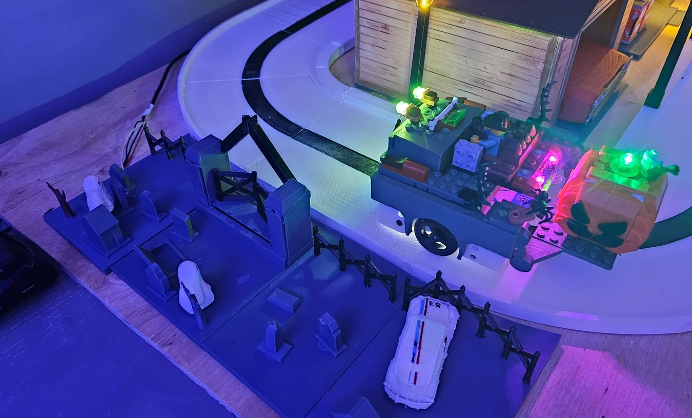
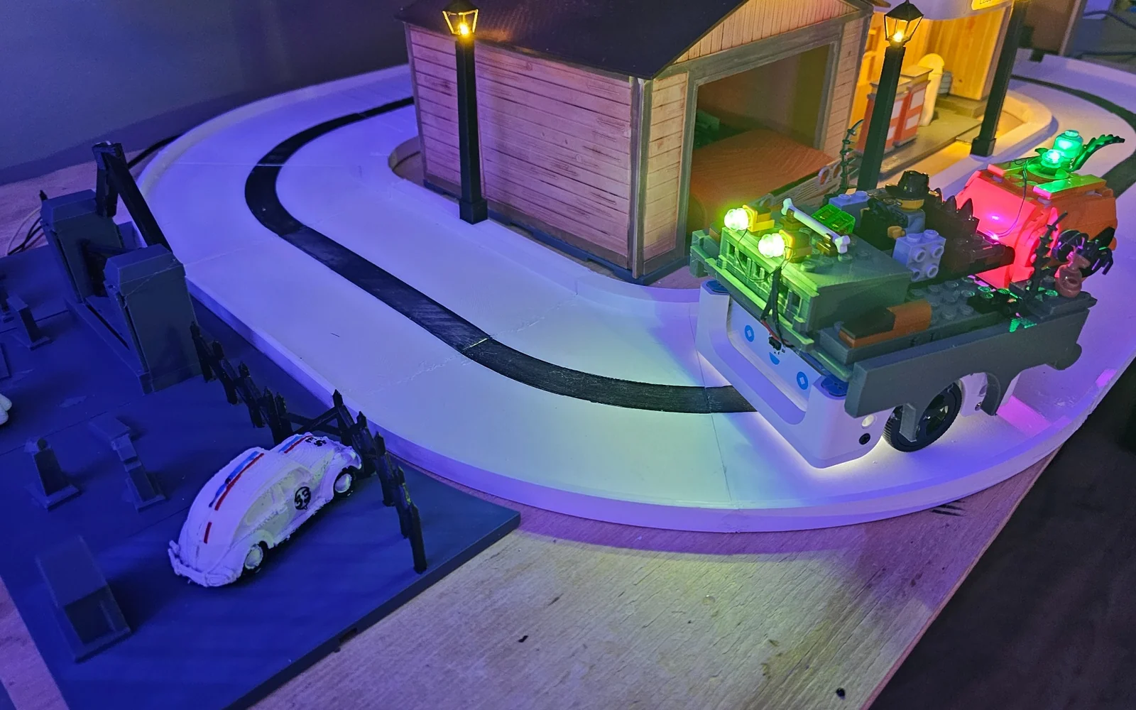
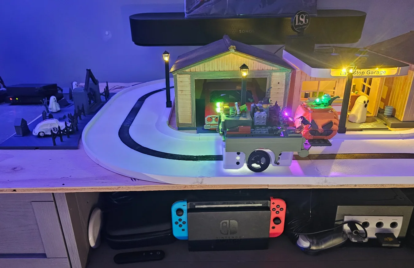
Photograph of the completed miniature garage, illuminated tractor, roadway and graveyardACTUAL BUILT DISPLAY · PHOTO
14-pieceCompleted modular roadway
Arduino AlvikMotor control and line-following
WLED + BLETimed lights and Bluetooth start/stop
OperationalFull Halloween show sequence
See it work

The real show — and the animated interpretation

The first video is footage of the completed, physical, operating installation. The second is a separately produced animated promotional short inspired by the same miniature world.

Actual completed display — live operating footage

See the real garage lights, Alvik tractor, completed roadway and graveyard encounter in the filmed physical demonstration.

Live-action video · Approximately 64 seconds · Recorded from the working tabletop display.

Animated promotional film

A cinematic interpretation based on the physical build. Atmosphere, characters and some scenery are stylized with AI animation; it is not footage of the functioning model.

Animated interpretation · 30 seconds · Separate from the real show video.

Built, not just rendered

Inside the finished world

A garage and office form the main building complex. The separate Alvik Home and graveyard are linked by a modular roadway. The robot follows the physical line rather than relying only on timed turns.

Working garage & office

The completed illuminated architectural complex, photographed in its actual tabletop setting.

Graveyard encounter
Graveyard encounter

Separate graveyard scenery beside the route; the animated ghost effect is part of the live show.

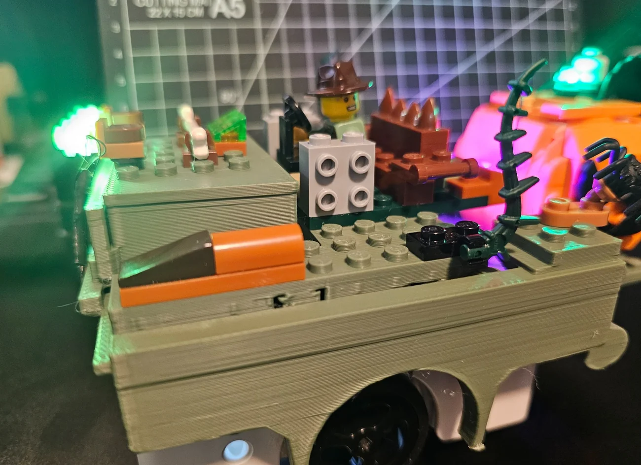
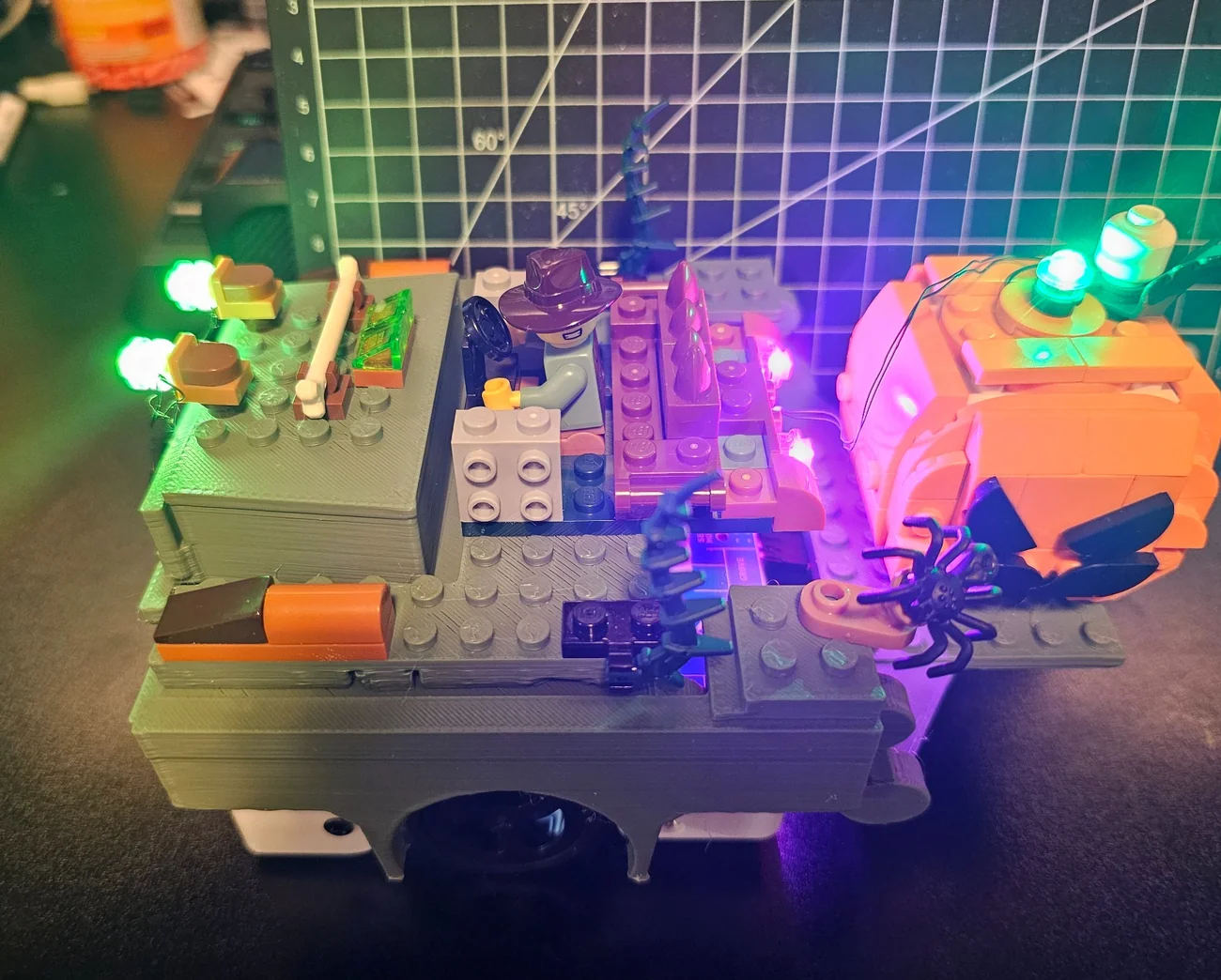
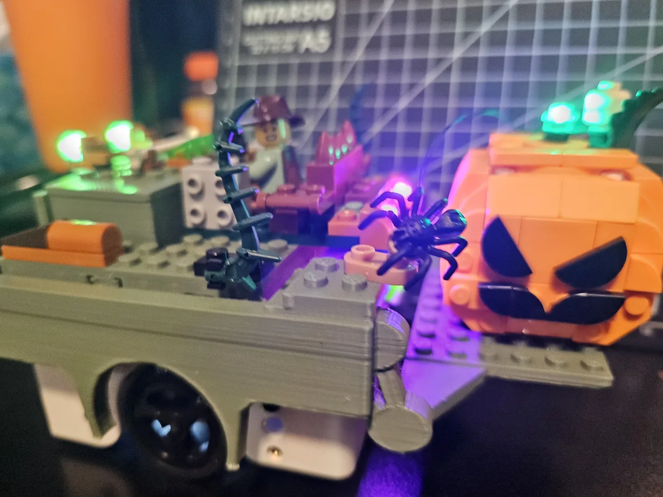
Alvik’s tractor body

The actual illuminated tractor / pumpkin-wagon character built around the Arduino Alvik.

Farmer & pumpkin details

A closer look at the tractor’s lights, driver, wagon and seasonal scenic elements.

Finished roadway and buildings

A physical installation with a line-following road connecting the main destinations.

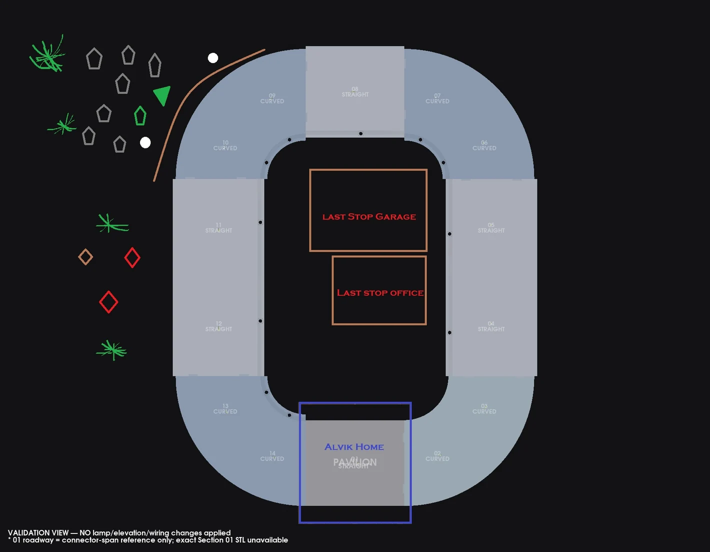
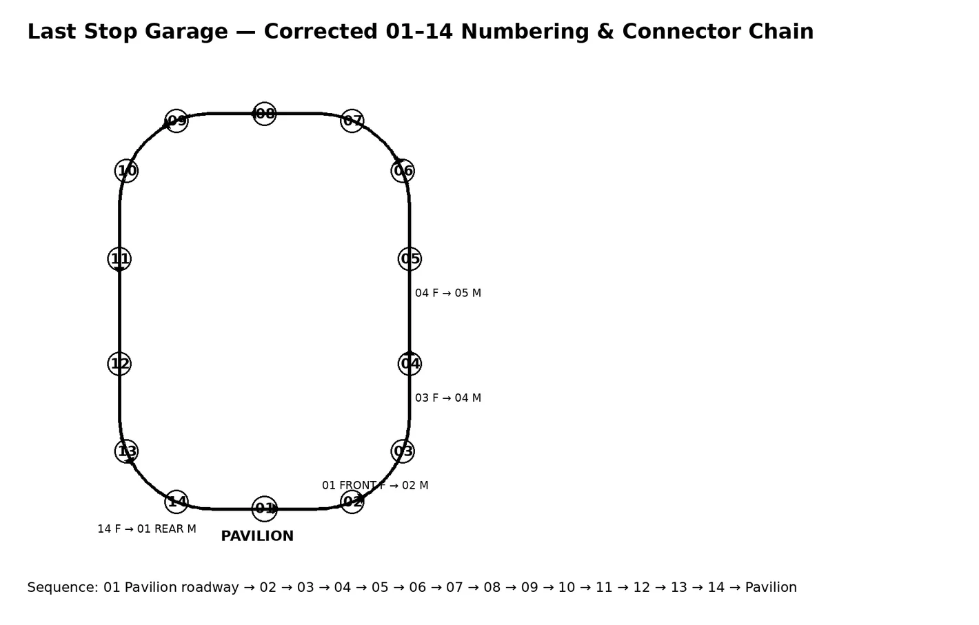
The 14-piece route plan

Route documentation for the approved roadway; diagram, not a photo of the finished model.

These are actual photographs of the project unless the caption explicitly identifies a diagram. The external home setting in certain photos provides scale and documents the working installation.

Show control

How the automated performance works

The approved production show integrates robot motion, physical roadway references, Bluetooth commands, building lights, street lamps, and timed WLED effects.

01 / START

The world lights up

After the show starts, street lighting fades on; building and store lights follow. The display establishes the scene before the tractor moves.

02 / DRIVE

Alvik follows the route

Bluetooth starts the show, while Alvik controls its own motors, follows the line, and responds to the physical course.

03 / ENCOUNTERS

Halloween story beats

The show includes a garage/store ghost cue, a pause at Herbie, and a startled reverse reaction at the graveyard ghost.

04 / ARRIVAL

Return to the garage

Alvik drives through the garage and stops at its final marker; the lights turn off and the show returns to READY.

TECH / CONTROL

BLE + WLED + MicroPython

An MIT App Inventor Bluetooth controller sends START/STOP commands; the approved Alvik MicroPython show coordinates the route and lighting cues.

MAINTENANCE

Manual USB charging

The running installation deliberately does not use wireless charging or automatic docking. Those earlier experiments are part of the archived design story.
Behind the print

The design and engineering archive

The project evolved from an experimental automatic charger into a reliable miniature show. These are authentic source photographs, diagrams, slicer images and early concepts—not all depictions are production hardware.

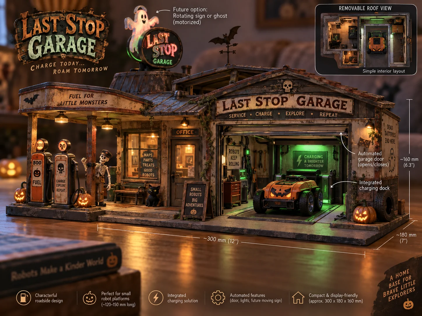
Original design vision

Concept artwork used to explore the visual identity; not a photograph of the finished build.

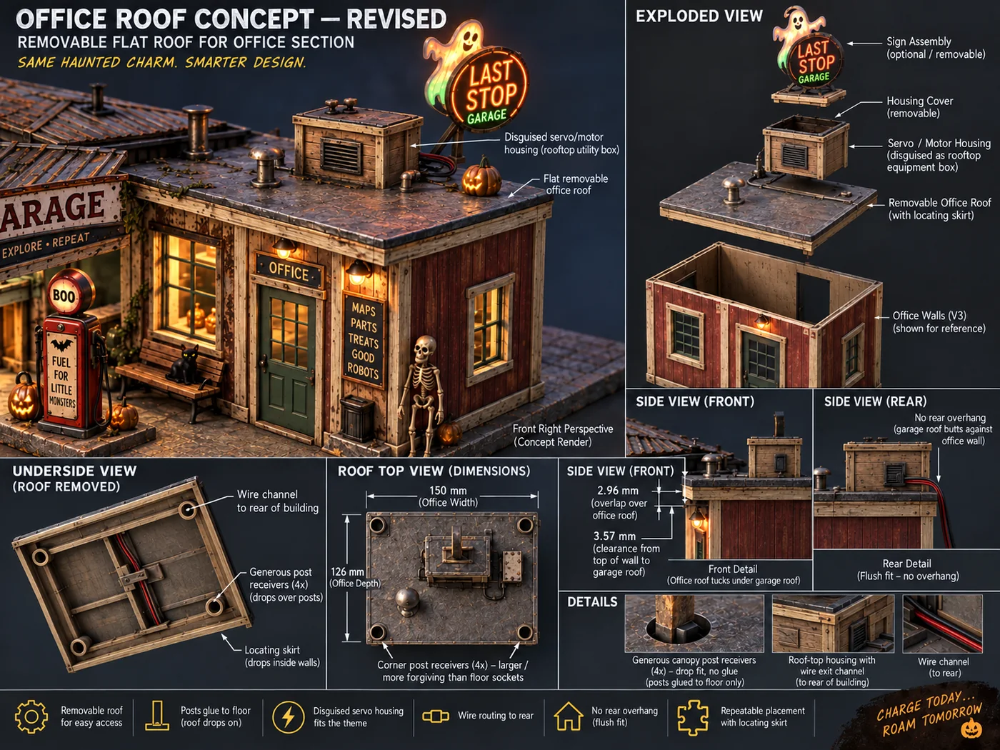
Roof design explorations

An illustrated concept board documenting revised office roof ideas, including service access.

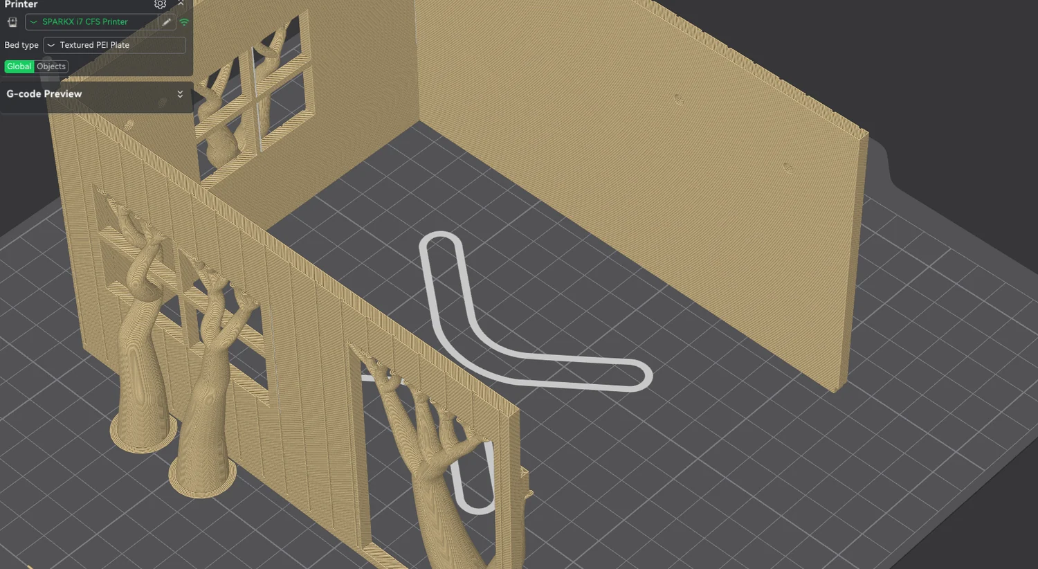
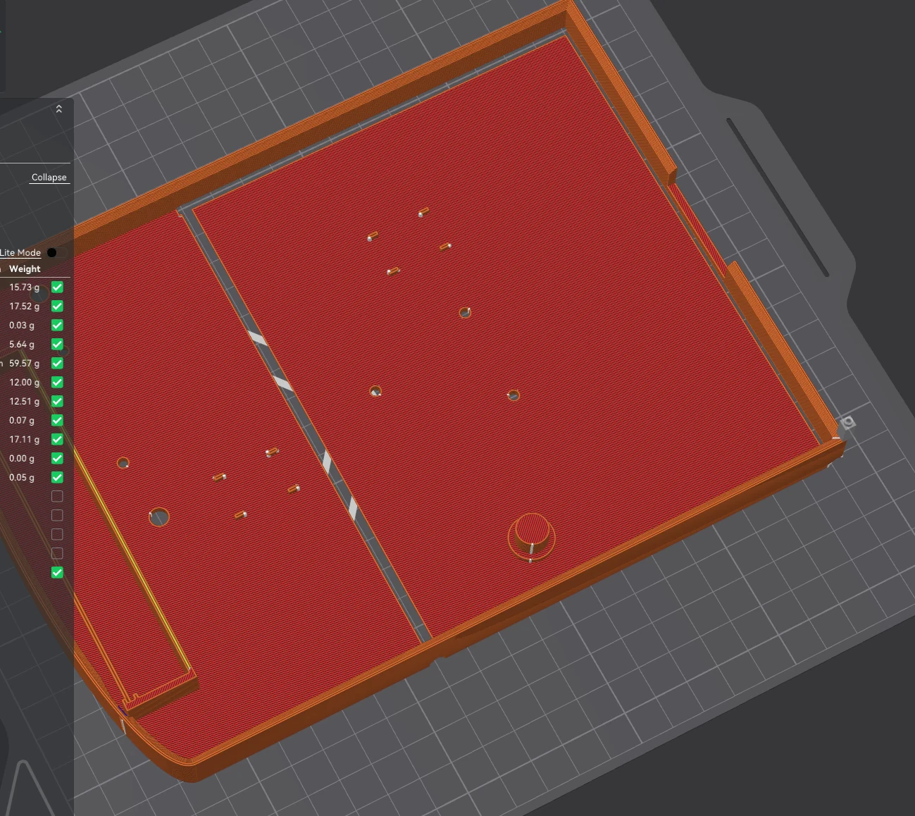
Garage wall CAD in the slicer

A real slicer preview showing the FDM fabrication stage for the modular wall geometry.

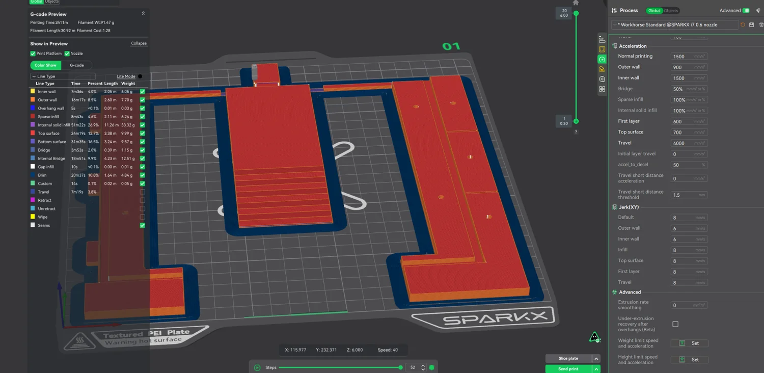
Production build-plate planning

Slicer layout from development of the garage/office modular printed components.

Office lower roof shell

Slicer view from the roof’s engineering and physical-fit development.

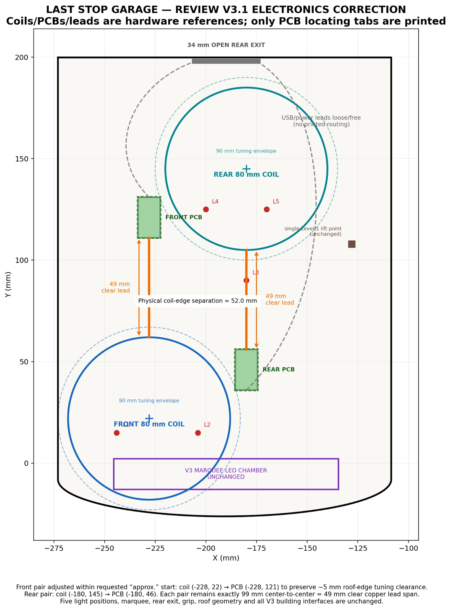
Office roof electronics planning

Engineering layout from an earlier V3.1 roof revision; development documentation, not final construction.

Alvik tractor development

Physical work on the tractor character, driver, lighting and pumpkin-wagon arrangement.

Road segment connector sequence

Diagram documenting how roadway pieces 01–14 connect.

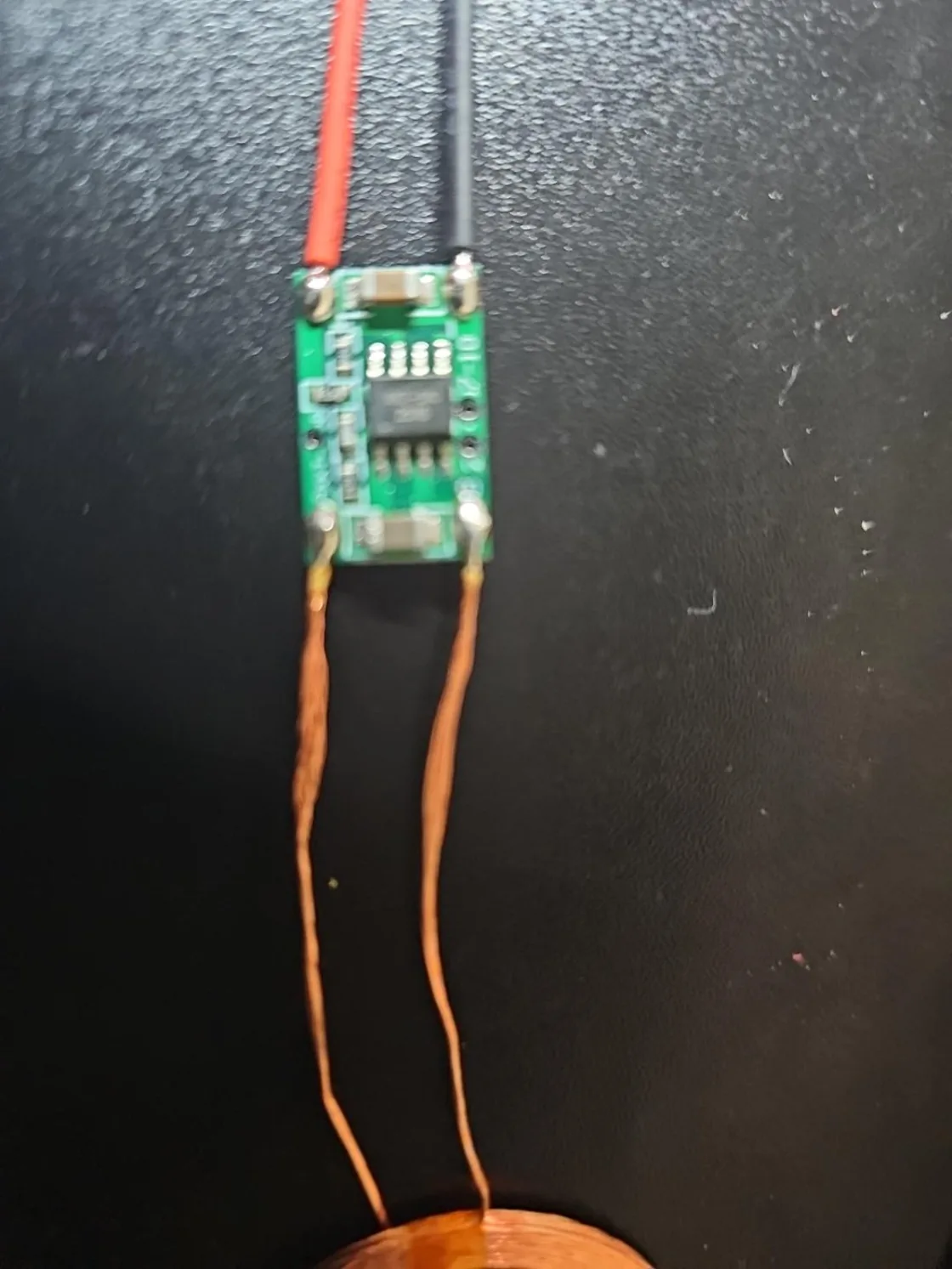
Prototype wireless power electronics

Real charging-system PCB from the experimental phase; not part of the operating production show.

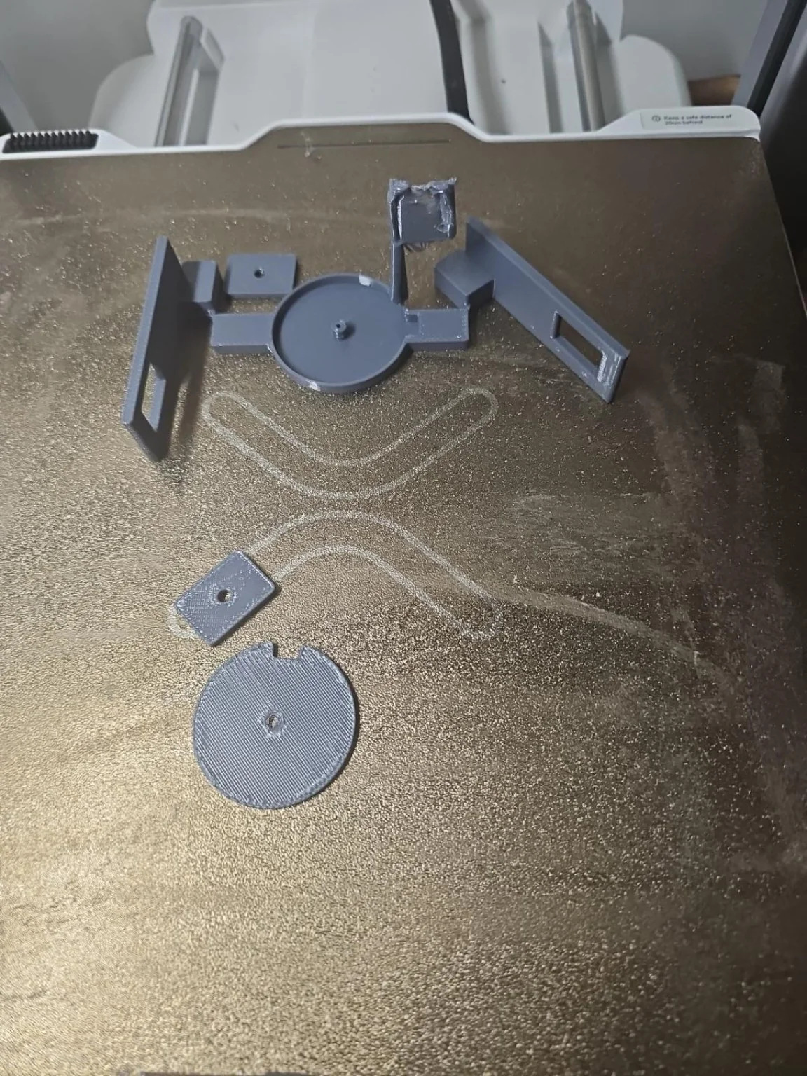
Experimental charging mount

Early 3D-printed mounting pieces for a charging concept later removed.

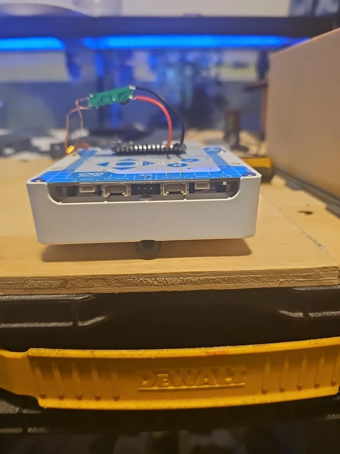
Receiver on the Alvik chassis

Historical test installation before manual USB charging became the reliable standard.

Development note: The wireless charging, self-docking system and automated door plans pictured in some archives are not operating features of the finished display. Wireless charging was retired in favor of manual USB charging after testing. Concept art and CAD diagrams are labeled separately from physical photographs.
From prototypes to performance

Why the final version works

The biggest project decisions were driven by what actually happened after printing and physical testing—not by accepting a CAD model simply because it looked correct.

Modular architecture

Garage and office walls, floors and roof sections were produced as separate serviceable pieces. The office roof went through geometry repairs, fit tests, and revised locating features before production.

Reliable operation first

Wireless power mounting and docking experiments were valuable, but removing them made the final experience more dependable. The 14-piece line-following route and WLED/BLE show were physically proven together.

Finished foundation · optional future work

Completed today, expandable tomorrow

Last Stop Garage is a completed working project. Future ideas are independent expansions, not requirements for making the current show operate.

Possible future controller

An ESP32-S3 scene master has been discussed for schedules, additional light branches and higher-level show commands. It remains a development concept. The approved Alvik standalone BLE/WLED show is preserved and continues to operate without it.

Build documentation and supplied project history: Last Stop Garage. Media are from the maker’s archive. Concept graphics are illustrations and the animated film is a creative interpretation, not a representation of unverified functions.